Parts of a Speaker: Every Component, Inside and Out
A speaker has two levels of parts. The system: cabinet, baffle, bracing, damping, port, crossover, binding posts and grille. The transducer: the drivers bolted to the front, each with its own cone, coil and magnet. This guide covers the system — every part, what it controls, and how it fails.
A complete speaker, cut in half
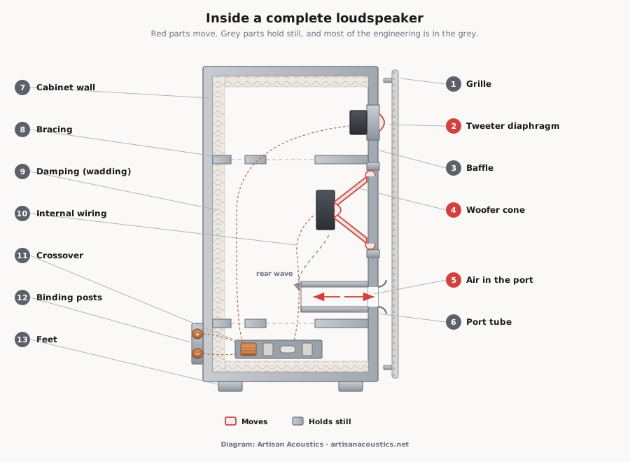
Three things in that drawing move air on purpose: the tweeter diaphragm, the woofer cone, and the slug of air in the port. Everything else exists to control what those three do.
What “parts of a speaker” actually means
Two honest answers, depending on how far in you are standing.
Stand back, and a speaker is a system: a box, a baffle with holes cut in it, bracing, wadding, a circuit of coils and capacitors, terminals, a grille.
Lean in, and the round things bolted to the front are transducers, each with an anatomy of its own — a different level of description, and a page of its own.
Most pages with this title answer the second question and skip the first. This one is the system.
The drivers
The drivers are the only parts that deliberately move air. Everything else here is in service of them.
A two-way has a woofer and a tweeter; a three-way adds a midrange, so the woofer can stop pretending it can do voices. More drivers is not better — the hard part is the hand-over.
| Driver | Roughly covers | Where it sits |
|---|---|---|
| Tweeter | 2 kHz and up | High on the baffle |
| Midrange | 300 Hz – 5 kHz | Between tweeter and woofer |
| Midwoofer | 50 Hz – 3 kHz | The one cone driver in most two-ways |
| Woofer | 40 – 500 Hz | Lower baffle |
| Subwoofer | 20 – 100 Hz | Usually its own cabinet |
| Compression driver | 500 Hz up, into a horn | Behind a horn mouth |
Conventions, not laws: what sets a driver’s band is cone area, moving mass and where the cone breaks up.
Inside each is a second set of parts, and those belong to the driver page. Every row links to it.
| Part of the driver | What it does |
|---|---|
| Cone | The piston. Pushes the air. |
| Surround | Seals the cone edge; permits axial movement only. |
| Spider | The same job from below, and recentres the coil. |
| Voice coil | The moving half of the motor. |
| Dust cap | Keeps grit out of the gap; stiffens the cone. |
| Magnet | Supplies the field the coil pushes against. |
| Basket | Holds it all in alignment for twenty years. |
The cabinet
A driver radiates from both faces of its cone, and the rear wave is the front wave inverted. Let them meet in open air and they cancel, which is why a driver held in your hand has almost no bass. The cabinet keeps them apart, and its harder job is doing that without joining in.
The baffle
The panel the drivers bolt to. Its edges are not neutral: a wavefront reaching a sharp edge re-radiates, and that interferes with the direct sound. Olson tested twelve enclosure shapes in 1950 — “in some of the enclosures the variation in response produced by diffraction exceeds 10 db”.5 Hence rounded edges.
Bracing
A panel big enough to hold a woofer is big enough to ring. The BBC named the result: wall resonances “can give rise to a coloured sound, the commonly used term ‘boxy quality’ adequately describing the result”. Struts “effectively increase the stiffness without significantly increasing the mass”, and a rod between opposing panel centres kills the fundamental mode.6
Damping and wadding
Two jobs, one word. Wadding — polyester, wool or foam in the cavity — absorbs the rear wave. Panel damping is a lossy layer on the walls, and the BBC’s finding on it contradicts the idea that heavier is better: damping “will have the maximum effect on a system having relatively low mechanical impedance, which implies a fairly thin panel”.6
Why MDF
Dense, stable, no grain to split along, machines cleanly, cheap. Plywood is stiffer for its weight, but MDF is consistent, which is what a production run needs. Local caveat: MDF and humidity are not friends, so a cabinet here wants a sealed finish everywhere.
The port
A port is a tube open at both ends, one in the cabinet and one in the room. It is not a hole for the bass to escape through — the usual mental model, and wrong in an interesting way.
The air in the tube has mass; the air in the box is a spring. Mass on a spring resonates, and near resonance the port radiates strongly, in phase with the cone. Below that, the cone unloads.
The mathematics is older than most assume. Thiele’s alignment tables reached the AES journal in 1971, but that paper is a reprint — the work was presented in Sydney in 1961.1 Small extended it into the analysis behind the modern method.2
Sealed against ported
It is a trade, and Small quantified both ends. In the passband the vented box is the better use of a cone — “peak diaphragm displacement xmax is substantially smaller for the vented-box driver”. Below tuning it reverses: the vented system is “more vulnerable to ... subsonic signals”.2 The cone flaps.
Boom is not a property of having a hole. It is a badly chosen alignment, or — far more often — a room mode excited by wherever you put the speaker. A sealed box in the wrong corner is just as boomy.
The inconvenient half: there is a real vented-box weakness, and the folklore is pointing next to it rather than at it. Below tuning the cone unloads and excursion climbs steeply.2
Port noise
Push enough air through a tube and the flow stops being orderly: “generally broad-band ‘chuffing’ noises due to fast moving air”, fixed since the late 1970s by “rounding the port ends with various radii, which led to the now common flared port”. The same paper adds a detail nobody quotes — “turbulence is actually preferred in matters of cooling the box”.4
The passive radiator
A port with mass instead of air: a cone and surround with no motor, tuned by the weight bolted on, used when a port of the required length will not fit. Small found it “capable of similar low-frequency performance”, and left a rule worth knowing — it “should possess a linear volume displacement limit at least twice that of the system driver”.3
The crossover
Physically the least glamorous object in the box: a board of inductors, capacitors and resistors. Functionally it decides which driver gets which part of the music, and it is where a great many speakers are won or lost.
A low-pass section sends bass to the woofer, a high-pass section treble to the tweeter, and steepness is quoted as an order — 6 dB per octave for first, 24 for fourth. Shallow slopes demand drivers that behave outside their band; steep ones shift phase harder.
Passive and active
A passive crossover sits after the amplifier, filtering a signal already at full power. An active one filters at line level, so every driver gets its own amplifier channel — less freedom in pairing, but the passive parts leave the driver’s path.
Why you cannot simply swap a driver
Textbook filter values assume the driver is a resistor — networks designed, in Linkwitz’s words, “under the idealized assumption that the drivers can be represented by frequency-independent resistors R = 8 ohms”. In practice “the filter element values must be modified and/or the driver input impedance made less frequency dependent”.8
So the crossover in your speaker is not a generic 2.8 kHz filter. It is tuned to one driver’s impedance curve, roll-off, sensitivity and baffle position. Fit a different driver and it is solving a problem that is no longer there — which is why the driver page says not to.
Spacing matters too. The drivers are not in the same place, so their outputs arrive by different path lengths, and near the crossover frequency that tilts the radiation pattern: “the main lobe ... shifts in direction and increases in amplitude”.7
Terminals, binding posts and bi-wiring
Five-way binding posts take bare wire, spades, pins or banana plugs. Their job is a large, tight, corrosion-free contact area, and their commonest failure is people not tightening them.
Get the polarity right: both speakers the same way round, red to red. Wire one backwards and its cone moves out while the other moves in, so bass cancels and the image collapses into a smear.
Four posts instead of two
Some speakers carry two pairs joined by metal straps. Take the straps off and the woofer and tweeter halves of the crossover are separate up to the terminals. Two cable pairs from one amplifier is bi-wiring; two amplifier channels is bi-amping, which is genuinely different.
We went looking for evidence and found very little: no controlled listening test we could locate, and one 1993 AES convention paper, paywalled with no retrievable abstract — so we will not cite a conclusion we have not read.
The most careful analysis we could read is Jim Lesurf’s, and it is a circuit model, not a measurement. It puts the level change at the crossover frequency, in decibels, at “approximately the same as the chosen cable series resistance in Ohms” — of the order of 0·1 dB — and his own verdict is that “it is debatable if any variations in practice will normally be large enough to be audible”.10
A very small calculable effect, and no listening evidence either way. Bi-amping is the one with a mechanism you can point at.
The grille
Cloth over a frame, held on with pegs or magnets. It stops fingers, pets and vacuum cleaners reaching the drivers.
Acoustically it is not free, and the cloth is not the problem — the frame is. D’Appolito measured a grille producing “severe response dips at 3, 5, and 14kHz and a broader peak at 12kHz”: the frame “presents an abrupt discontinuity on the baffle”, generating “a secondary wave ... with reverse phase”. Because his frame was only 7 mm thick it “has little effect on frequencies below 3kHz”.11
Whether that matters is a separate question from whether it is measurable. An informal study of four perforation patterns found the differences “much more measurable than audible”.12
One claim we cannot support, having tried: that manufacturers always measure grille-off. We found no standard requiring it, published measurements appear both ways, and IEC 60268-5 does not address grilles.
So: leave it on if you prefer it on. If you are chasing the last decibel of treble, take it off — and leave it off, because a grille you keep swapping is one you never listen through consistently.
Every part at a glance
| Part | Usually made from | What it controls | How it fails |
|---|---|---|---|
| Cabinet walls | MDF, plywood, HDF | Separates front and rear waves; panel resonance | Colouration; joints opening in humidity |
| Baffle | MDF, plywood, stone composite | Driver spacing and edge diffraction | Bolts loosening; gasket leaking |
| Bracing | MDF, plywood, hardwood dowel | Raises panel resonance out of the way | A glue joint letting go, which buzzes |
| Damping and wadding | Polyester, wool, foam, bitumen pads | Absorbs the rear wave; damps the panels | Settling, coming unstuck, blocking a port |
| Port | Plastic or card tube, often flared | Extends bass; sets tuning frequency | Turbulence noise; rattling if loose |
| Passive radiator | Weighted cone and surround, no motor | A port’s job in less space | Surround perishing; running out of travel |
| Crossover | Inductors, capacitors, resistors | Which driver gets which frequencies | Capacitors drifting; cracked solder |
| Binding posts | Brass, often plated | The connection to your amplifier | Corrosion; a snapped solder tag |
| Internal wiring | Stranded copper | Carries the signal to the drivers | Cold joints; spades working loose |
| Grille | Cloth over MDF or plastic frame | Physical protection | Sagging cloth; diffraction; perished pegs |
| Feet or spikes | Rubber, elastomer, metal spikes | Couples or decouples cabinet from floor | Rocking; rubber hardening |
| Drivers | See the driver page | Actually moving the air | Surround rot; open or rubbing voice coil |
The pattern is in the last column: almost nothing here fails suddenly. These parts degrade slowly enough that you adapt as they go.
How a speaker fails, and which part did it
Driver faults belong to the driver page, which lists them there. These are the ones where the drivers are fine and something else is not.
- A buzz on certain bass notes only. Press the driver bolts, the grille, the port tube, the terminal cup. A buzz that changes when you press something has told you where it lives.
- Huffing on deep bass. Port turbulence — you are past the airflow the port can pass cleanly.4 Nothing is broken.
- One speaker thinner than the other. Check the posts and straps, then the crossover: electrolytic capacitors drift with age, and a drifted capacitor moves the crossover frequency rather than silencing anything, so the speaker still works — just wrongly.
- Sound cutting in and out when you nudge the cable. The connection: a loose post, or a solder tag fatigued inside the terminal cup.
- A boxy colouration that was not there before. Wadding that has settled or come unstuck — or panel resonance that damping used to keep in check.6
- A cabinet joint you can see. Humidity. MDF takes up moisture, swells and eventually delaminates.
If the fault changes when you press something, it is mechanical and probably fixable. If not, the box has to come open.
Common questions about speaker parts
What are the main parts of a speaker?
A cabinet, a baffle, one or more drivers, a crossover, internal wiring and binding posts. Most add bracing and damping inside, many add a port, and most ship with a grille and feet.
What are the parts and functions of a speaker?
The cabinet keeps the front and rear waves apart and stays quiet doing it. The baffle carries the drivers and sets their spacing. The drivers turn electricity into air movement. The crossover splits the frequencies between them. The port extends the bass by resonating. The binding posts connect the amplifier.
What are the internal components of a speaker?
The rear of each driver, the crossover board, the internal wiring, the bracing, the damping or wadding, the inner end of the port tube, and the back of the terminal cup. On a passive speaker there is no electronics beyond the crossover.
What are the parts of a speaker called?
The box is the cabinet or enclosure, and its front is the baffle. The round drivers are the woofer, midrange and tweeter — not “speakers”, though almost everybody calls them that. The tube is the port, the circuit is the crossover, the connectors are binding posts.
What are speaker components?
The phrase does three jobs. In a hi-fi shop it means the separate boxes in a system — source, amplifier, speakers. In loudspeaker engineering it means the parts inside one speaker, which is this page. “Component speakers” for a car means a set sold as separate woofer, tweeter and crossover.
What are the parts of a music speaker?
The same parts as any other passive loudspeaker. “Music speaker” is not an engineering category — a speaker for music, one for cinema and one for public address differ in how they are voiced, not in what they are made of.
Where to go from here
One level in is the transducer itself: every part of a speaker driver, and how to read those parts off a datasheet.
If the cone material argument brought you here, start with what TeXtreme® actually is, or the comparison against Kevlar and conventional carbon fibre.
And if you mainly want to know which speaker to buy, that is a different answer for every room. We build ours around SB Acoustics and SB Audience drivers.
Come and listen.
Bring your favourite tracks. Leave with something you'll keep for decades. No pressure, no commission-chasing.
References and further reading
- Thiele, A. N. “Loudspeakers in Vented Boxes, Parts 1 and 2.” JAES, vol. 19, no. 5, 1971, pp. 382–392, and no. 6, pp. 471–483 — a reprint of work presented in 1961. Free scan.
- Small, R. H. “Vented-Box Loudspeaker Systems, Parts 1–4.” JAES, vol. 21, nos. 5–8, 1973, pp. 363–372, 438–444, 549–554, 635–639. Free scan.
- Small, R. H. “Passive-Radiator Loudspeaker Systems, Parts 1 and 2.” JAES, vol. 22, no. 8, 1974, pp. 592–601, and no. 9, pp. 683–689. Free scan.
- Salvatti, A., Devantier, A., and Button, D. J. “Maximizing Performance from Loudspeaker Ports.” JAES, vol. 50, no. 1/2, 2002, pp. 19–45. Free scan.
- Olson, H. F. “Direct Radiator Loudspeaker Enclosures.” Audio Engineering, vol. 35, no. 11, 1951, pp. 34, 36, 38, 59–64; reprinted in JAES, vol. 17, no. 1, 1969, pp. 22–29. Free PDF.
- Harwood, H. D., and Mathews, R. “Factors in the Design of Loudspeaker Cabinets.” BBC Research Department Report RD 1977/3, January 1977. Free PDF.
- Linkwitz, S. H. “Active Crossover Networks for Noncoincident Drivers.” JAES, vol. 24, no. 1, 1976, pp. 2–8. Free scan, author’s site.
- Linkwitz, S. H. “Passive Crossover Networks for Noncoincident Drivers.” JAES, vol. 26, no. 3, 1978, pp. 149–150. Free scan, author’s site.
- Bohn, D. “Linkwitz-Riley Crossovers: A Primer.” RaneNote 160, Rane Corporation, October 2005. Free.
- Lesurf, J. “Bi Wiring to Loudspeakers.” Audiomisc, University of St Andrews. Free. A circuit model, not a measurement, and not peer-reviewed; the figures quoted are on its third page.
- D’Appolito, J. “Testing Loudspeakers: Which Measurements Matter, Part 1.” audioXpress, September 2008. Free.
- Liddle, S., with Brown, P. “Does the loudspeaker grille effect the frequency response?” ProSoundTraining, 21 July 2011. Free. An informal study; title as published.
Where a paper is paywalled a freely readable scan is linked beside the canonical citation; AES papers of this era carry no DOIs. No specification here is ours.