What Is a Speaker Driver? Parts, Types and How They Work
A speaker driver is the transducer inside a loudspeaker that converts an electrical audio signal into sound: current through a voice coil suspended in a magnetic field produces a force, the force moves a cone, and the moving cone moves air. Everything else in the box — the cabinet, the crossover, the wiring, the badge on the front — exists to help it do that, or to stop it doing it badly. Here is every part inside one, what each part controls, and how to read those parts off a datasheet.
What is a speaker driver?
Mechanically it is very simple. A coil of wire sits in a magnetic field. Music-shaped current flows through the coil, the field pushes the coil back and forth, the coil drags a cone with it, and the cone shoves air at your ears.
That is the entire job. Everything below is detail about how to do it without adding anything of its own.
Most people say speaker when they mean driver. The speaker is the whole loudspeaker — cabinet, crossover, terminals, and the drivers bolted to the front. The driver is the round thing doing the work. Get that distinction straight and you are already ahead of most of the internet, including several manufacturers.
The cutaway
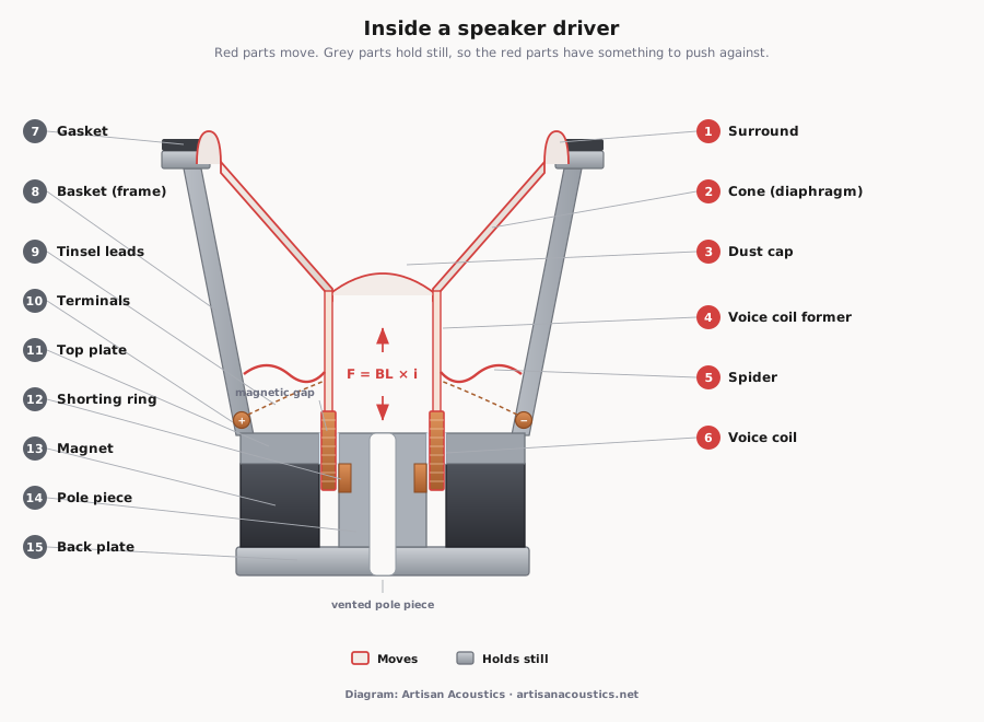
Here is the whole object, before we take it apart.
Three different things get called a “driver”
Let us clear the most common confusion first, because search engines cannot tell these apart either.
| What people mean | What it actually is |
|---|---|
| Speaker driver (this article) | The physical transducer — cone, coil, magnet. A component you can hold. |
| Speaker | The complete system: one or more drivers, a cabinet, a crossover, terminals. |
| Audio driver | Software. A file on your computer that lets the operating system talk to a sound card. Nothing to do with either of the above. |
If you arrived here because Windows said your audio driver needed updating, we are very sorry, and it is the third one.
How a speaker driver works
Here it is in one paragraph.
Your amplifier sends a varying current down two wires. That current runs through a coil of wire — the voice coil — suspended in the narrow gap of a permanent magnet. A current-carrying wire in a magnetic field experiences a force at right angles to both. Because the coil is wound in a circle inside a radial field, that force points along the coil’s axis: straight in, or straight out. Reverse the current and the force reverses with it. The coil is glued to a cone, so the cone goes along for the ride, and a moving cone moves air. Air pressure rising and falling is what your ears report as sound.
The force is not vague. It is F = BL × i — where i is the current your amplifier supplies, B is the flux density in the magnet gap, and L is the length of wire actually sitting inside that gap.
B and L are fixed by how the driver was built, so they get bundled into one number: BL, the force factor, measured in tesla-metres.1 It is the most useful number on a datasheet, and we will come back to it.
The parts that move
Everything inside a driver belongs to one of two groups: the parts that move, and the parts that hold still so the moving parts have something to push against. We will take them in that order, because that is the order in which they matter.
The cone
The cone — properly, the diaphragm — is the piston. Its job is to be perfectly rigid, weigh nothing, and swallow its own vibrations. These requirements are mutually exclusive, which is why cone material has been an argument for a century.
Two numbers matter. Effective piston area (Sd) is how much air the cone can get hold of. Moving mass (Mms) is how much the motor has to shift, and it includes the slug of air dragged along in front of the cone — which is why datasheets say including air load.
Above a certain frequency the cone stops behaving as one solid object and starts flexing in rings and petals, different parts moving in different directions at the same time. This is cone breakup, and it is audible, usually as hardness or sting. The governing property is stiffness against weight: to stay pistonic, a cone wants the highest possible stiffness-to-weight ratio, which in materials terms means the highest ratio of Young’s modulus to density.5 Paper, aluminium, glass fibre, woven composites and spread-tow carbon are all attacks on that same problem from different directions.
You will read that a large woofer cannot keep up with fast music. It is a tidy story and it is not what happens. What actually limits a large cone at high frequencies is that it breaks up, and that it beams — once the wavelength gets short compared with the cone’s circumference, output collapses into a narrow forward lobe instead of spreading into the room.78
Worth adding, because it is the part people find surprising: when someone measured this by bolting extra mass to a woofer and firing an impulse at it, the mass-loaded driver’s transient arrived at the same time as the standard one. The response that did arrive late was the one loaded with extra inductance.9 Mass changes what a driver does. It does not make it late.
The surround
The rubber, foam or fabric roll joining the edge of the cone to the frame. It does two things at once: it seals the front of the cone from the back, and it lets the cone move in and out while resisting any attempt to move sideways.
It is also the part most likely to kill your speakers. Foam surrounds perish — ten to twenty years, faster in heat and humidity, a sentence with particular weight in Singapore and Malaysia. A crumbling surround is the most common reason a perfectly good vintage driver stops working, and one of the few faults genuinely worth repairing.
The spider
The corrugated fabric disc — properly the damper, though nobody calls it that — sitting below the cone and gripping the coil former. Same job as the surround, from the other end: permit axial movement, forbid everything else, and return the coil to centre when the music stops.
Together the surround and the spider are the suspension, and between them they set compliance (Cms) — how springy the moving assembly is. Compliance is not constant either; it stiffens as the assembly moves away from rest, and that nonlinearity is its own distortion mechanism.1 Compliance and moving mass together give you the driver’s resonant frequency, and we will show you exactly how in a moment.
This one finally has a peer-reviewed answer, and it is not the one the forums wanted. A 2025 study in Applied Sciences ran the experiment properly and found measurable changes in impedance and amplitude response after burn-in, but changes “inaudible to the average listener” — and listeners rated the sound the same whether a speaker had been burned in or not.10
The genuinely interesting finding is the one nobody quotes. The variation between two speakers of the same model was larger than the change produced by burning either of them in. That is production tolerance, not use. Play them, by all means. Just do not schedule the epiphany.
The former
The thin cylinder the voice coil is wound onto, bridging coil to cone. It is the least-discussed part of a loudspeaker and one of the most consequential, because it is the thermal path. The coil gets hot; the former decides where that heat goes.
Kapton is light and a good insulator — which also makes it a good heat insulator. Aluminium conducts heat away far better, but is electrically conductive, so it behaves as a shorted turn in the magnetic field and brings losses of its own. Glass fibre sits in between. There is no free lunch here, only a choice about which bill to pay.
The voice coil
A coil of wire wound onto the former, sitting in the gap of the magnet. Current in, force out. It is the moving half of the motor, and the part every other part is arranged around.
It is also where the energy goes. Small put the efficiency of a direct-radiator system at “of the order of one percent”.2 The other ninety-nine per cent becomes heat in the coil. Vented pole pieces, aluminium formers, ferrofluid, cast baskets with open spokes — almost every motor design decision is a heat-management strategy wearing a different hat.
And heat has an audible consequence. As the coil warms, its resistance rises, so a constant-voltage amplifier drives less current into it, so you get less output.6 Turn it up and it gets quieter than it should be. This is power compression, and it is why a driver’s rated power handling tells you when it dies, not when it stops behaving.
The dust cap
The dome in the middle. It keeps debris out of the magnet gap, which is the stated purpose and the least interesting thing about it. It is also glued across the mouth of the cone, so it stiffens the whole moving assembly and radiates a little on its own account.
Some drivers replace it with a phase plug — a fixed bullet mounted to the pole piece that does not move with the cone. It exposes the coil to more air for cooling, and evens out the path lengths from different parts of the cone to your ear.
The parts that stay still
The magnet
The magnet does not move. It sits there producing a field, and the coil does all the work inside it. Ferrite is the big grey ring; neodymium is the small expensive one; Alnico is what your grandfather’s had. There is a longer answer to why speakers use magnets at all, but the short one is that nothing else makes a controllable force this cheaply.
Which brings us to the oldest piece of hi-fi folklore going.
The magnet’s contribution is BL — force. More force means the cone is started and stopped harder, which is control, not reach. What sets low-frequency output is how much air you displace, and that is piston area and excursion multiplied together: a big cone with nowhere to travel buys you nothing, and neither does a huge motor on a small one. Small’s analysis is blunt about the cone on its own — diaphragm area “does not appear explicitly in the small-signal response, small-signal efficiency, or displacement-limited power ratings”.2
Does a stronger motor help at all? Yes, but not in the way the folklore means. Raising BL raises efficiency and lets you use a smaller box, while tilting the response so it needs equalisation to come back flat.11 It buys sensitivity and cabinet volume. It does not buy octaves.
In fairness: we have found no paper that rebuts “bigger magnet, deeper bass” in those words — nobody writes papers to refute folklore. The rebuttal above is drawn from what the displacement and efficiency equations actually contain.
Nor is ferrite the poor relation. Neodymium is smaller, lighter, dearer, and likes heat considerably less — which is why drivers built to be leaned on all day still wear enormous grey rings.
The top plate, back plate and pole piece
The steel around the magnet, whose entire purpose is to take the magnet’s field and concentrate it into one narrow, intense, precisely-shaped gap where the coil lives. The pole piece runs up the middle; the top plate forms the outer wall of the gap; the back plate closes the magnetic circuit underneath.
Gap height and coil height between them set how far the driver can travel before the force starts changing — which is a specification, and we will calculate it shortly. The pole piece is often drilled through, which lets air escape from behind the dust cap instead of compressing, and lets heat out.
The shorting ring
A ring of copper or aluminium in the motor gap. It appears on essentially no other article about speaker drivers, and it is one of the more meaningful things a manufacturer can put in a motor.
The problem it solves: the voice coil is an inductor, and its inductance changes depending on where it sits and how much current is flowing. Inductance that varies with the signal is, by definition, distortion. Klippel is explicit about the fix — inductance “can be significantly reduced by placing conductive material (usually rings or caps made of aluminum or copper) on the pole piece”, and placed correctly the inductance curve “can be significantly linearized”.1
You will see it called a shorting ring, a Faraday ring, a demodulation ring or a copper cap. SB Acoustics’ Satori WO24 and WO34 woofers carry dual shorting rings and their beryllium-dome tweeters carry dual copper caps, per the manufacturer’s own descriptions. On SB Audience’s Rosso cone drivers, a D in the model number is the manufacturer’s shorthand for exactly this.
The basket
The frame everything bolts to. Stamped steel is cheap and adequate. Cast aluminium is stiffer, damps better, dissipates heat, does not ring — and costs more.
Its job is to hold the gap and the cone in perfect concentric alignment for twenty years while being vibrated several hundred times a second by the thing bolted to it. If the basket flexes, the coil rubs. A rubbing coil is a dead driver.
Terminals, tinsel leads and the gasket
The unglamorous ones. Terminals take the wire from your amplifier. Tinsel leads are the flexible braided wires carrying current from the terminals onto the moving coil — they flex on every single cycle for the life of the driver, which makes them a real engineering problem and a common failure point. The gasket seals the driver to the baffle, so the cabinet is airtight where you think it is.
Every number on a datasheet is one of these parts
This is the part nobody else does, so here it is in full.
Below is the published parameter set for the SATORI MW16TX-4, a 6½-inch midwoofer, exactly as SB Acoustics publishes it. None of these are our numbers. What we are going to do is show you that every one of them is a part you have just read about — and that the sheet can be checked against itself.
| Parameter | Value | Which part that is |
|---|---|---|
| Free air resonance, Fs | 29 Hz | Suspension springiness against moving weight |
| Effective piston area, Sd | 119 cm² | The cone |
| Moving mass incl. air, Mms | 12.6 g | Cone + coil + former + dust cap + air load |
| Compliance, Cms | 2.39 mm/N | Surround + spider |
| Force factor, BL | 5.2 Tm | Magnet field × wire in the gap |
| Magnetic flux density | 1.17 T | The magnet and the steel around it |
| Voice coil diameter | 36 mm | The coil |
| Voice coil height | 17 mm | The coil |
| Air gap height | 5 mm | The top plate |
| Linear coil travel (p-p) | 12 mm | Coil height against gap height |
| Mechanical resistance, Rms | 0.46 kg/s | Losses in the suspension |
| DC resistance, Re | 3.4 Ω | The coil, as your amplifier sees it |
| Voice coil inductance, Le | 0.15 mH | The coil again, at high frequencies |
Now treat those as physics rather than as marketing.
How far can it move? The coil is 17 mm tall, the gap is 5 mm. The overhang is the difference, split between the two ends: (17 − 5) ÷ 2 = 6 mm each way, 12 mm peak to peak. The datasheet says 12 mm. That is not a coincidence, it is the definition.
Why 29 Hz? Resonance is springiness against weight: Fs = 1 ÷ (2π√(Mms × Cms)). Put in 12.6 g and 2.39 mm/N and you get 29.0 Hz. Change the spider and that number moves.
How much wire is in the gap? BL divided by flux density: 5.2 ÷ 1.17 = 4.44 metres. The coil is 36 mm across, so its circumference is 113 mm — meaning roughly 39 turns are sitting in the field at rest. That is the L in F = BL × i, and you just measured it off a page.
And the rest falls out too. Qms, from mass, resonance and mechanical losses, gives 4.99 against a published 5.0. Qes, which adds BL and Re, gives 0.289 against a published 0.29. Qts combines them at 0.273 against a published 0.27. Vas — the volume of sealed air that would be as springy as the suspension — comes from piston area and compliance, and lands on 48.0 litres, which is exactly what is printed.
Arithmetic ours, from SB Acoustics’ published values, rounded as they round them. We have generated no specifications: every input above is the manufacturer’s.
The point is not the sums. The point is that a driver datasheet is not a list of marketing claims. It is a physical description of an object, it is internally consistent, and once you know what the parts do you can read it — and catch anyone whose numbers do not add up.
Types of speaker driver
Drivers are specialised by frequency, because none of them does the whole range well. Ask a cone big enough for 30 Hz to also do 15 kHz and you have asked it to be two incompatible objects.
| Type | Roughly covers | Typical size |
|---|---|---|
| Subwoofer | 20–100 Hz | 8–21″ |
| Woofer | 40–500 Hz | 6–15″ |
| Midwoofer | 50 Hz–3 kHz | 4–8″ |
| Midrange | 300 Hz–5 kHz | 2–6″ |
| Tweeter | 2–20 kHz | 19–29 mm dome |
| Super-tweeter | 8 kHz and up | 19–25 mm |
| Full-range | 80 Hz–15 kHz, with compromises | 3–8″ |
| Compression driver | 500 Hz–20 kHz, into a horn | 25–75 mm |
Those sizes are conventions, not laws. What actually sets the useful range is piston area, moving mass, and where the cone starts breaking up.
Everything above is a dynamic driver: coil, magnet, cone. It is not the only way to move air.
| Alternative | How it moves air | The trade |
|---|---|---|
| Ribbon | Current through a thin corrugated foil suspended directly in the field | Almost no moving mass, superb top end; fragile, low sensitivity, limited power |
| AMT | A pleated diaphragm that squeezes air out of its folds | Fast, high output for its size; complex to manufacture |
| Planar magnetic | Conductors printed onto a large flat film between magnet arrays | Large radiating area, low distortion; needs space, low sensitivity |
| Electrostatic | A charged film pulled between two perforated plates | Extraordinary transparency; needs a power supply, dislikes humidity, and bass costs area |
| Balanced armature | A tiny magnetically-driven reed, used in in-ear monitors | Small and efficient; narrow bandwidth, so they get used in groups |
If you have ever read a spec sheet that says “dynamic driver” and wondered why anyone bothered specifying it — that is why.
How to tell if a driver is blown
In order of likelihood, and all diagnosable at home:
- No sound at all, and no continuity across the terminals. Open voice coil, usually thermal. Terminal, and not repairable in place.
- Scraping or rubbing at low level. The coil is touching the gap. Press the cone gently and evenly with your fingertips — it should move silently. Rubbing means the coil, former or basket has deformed.
- Distortion only when it gets loud. Suspension or coil damage, or you have simply run out of excursion.
- Splits in the surround, or a cone sitting crooked. Perished surround or a sagged spider. The most common fault by a distance, and the most repairable.
- Works, but sounds thin and lifeless. Check the tinsel leads. A partly broken lead makes intermittent contact.
Cone drivers can usually be reconed. Domes and compression drivers usually take a replacement diaphragm. Neither is a tragedy.
Frequently asked questions
What does a speaker driver do?
It converts an electrical audio signal into sound. Current through the voice coil, sitting in a magnetic field, produces a force; the force moves a cone; the cone moves air.
What is the difference between a speaker driver and a speaker?
The driver is the transducer — one component, the round thing that moves air. The speaker is the finished system: a cabinet, a crossover, terminals, and one or more drivers bolted to the front. One speaker usually contains two or three drivers.
What is the difference between a driver and a woofer?
A woofer is a driver. “Driver” is the category — any transducer that turns an electrical signal into sound. “Woofer” names one kind of driver by the band it covers, roughly 40 Hz to 500 Hz. Tweeters, midranges, subwoofers and full-range units are all drivers too. Asking whether to buy a driver or a woofer is like asking whether to buy a vehicle or a van.
What are the main parts of a speaker driver?
Cone, surround, spider, voice coil former, voice coil and dust cap all move. Magnet, top plate, back plate, pole piece, shorting ring, basket, tinsel leads, terminals and gasket stay put.
Does speaker driver size matter?
For bass, yes — but only as half of a product. Output depends on cone area multiplied by excursion, so a large cone that cannot travel is no better than a small one that can. Above the bass it matters less than the motor, the suspension and the cone material.
What is the voice coil former made of?
Usually Kapton, aluminium or glass fibre. The choice is mostly about heat: aluminium conducts it away from the coil, Kapton does not but is electrically inert.
Can I replace just one driver in a pair of speakers?
You can, and you generally should not, unless the replacement is genuinely identical. The crossover is designed around a specific driver’s behaviour, and a pair of speakers that no longer match is worse than one speaker that does not work.
What is the 83% rule for speakers?
It is a speaker placement rule of thumb, it has nothing to do with drivers, and almost everything written about it online is wrong — so it is worth answering properly.
The rule is attributed to Jim Smith, author of Get Better Sound: set the distance between the two tweeters at about 83% of the distance from each tweeter to your ears. Speakers 10 ft apart, then, put you about 12 ft from each of them — a narrower triangle than the classic equilateral setup.
Two warnings. First, the articles currently ranking for this phrase state the ratio backwards, describing the listening distance as 83% of the speaker spacing, which inverts the geometry; they also appear to be one article syndicated across several sites rather than several independent sources. Second, there is a fabricated definition circulating that claims the 83% rule is about matching speaker impedance to an amplifier’s minimum rating. No such rule exists — amplifier minimum impedance is a hard limit, not a percentage margin.
It is a subjective setup heuristic from an experienced listener. It is not engineering, and it is not about drivers. Try it by all means — your room will have opinions.
Where to go next
If you want the level above this one — cabinets, ports, crossovers, binding posts, and what the box does to the driver bolted to it — that is the parts of a speaker.
Cone material is the argument that never ends, and the one place where a genuinely new answer has turned up in the last decade — start with what TeXtreme® actually is, or the comparison against Kevlar and conventional carbon fibre.
If you now know what a driver is and want to know which kind of speaker to put it in, that is a different question with a different answer for every room.
And if you want to look at real ones: we distribute SB Acoustics and SB Audience drivers in Singapore and Malaysia, and every parameter discussed above is published for every model. Ask before you buy and we will send you the sheet.
Come and listen.
Bring your favourite tracks. Leave with something you'll keep for decades. No pressure, no commission-chasing.
References
- Klippel, W. “Tutorial: Loudspeaker Nonlinearities — Causes, Parameters, Symptoms.” Journal of the Audio Engineering Society, vol. 54, no. 10, 2006, pp. 907–939. Free author preprint.
- Small, R. H. “Direct-Radiator Loudspeaker System Analysis.” JAES, vol. 20, no. 5, 1972, pp. 383–395. Free scan.
- Thiele, A. N. “Loudspeakers in Vented Boxes, Parts 1 and 2.” JAES, vol. 19, no. 5, 1971, pp. 382–392, and no. 6, pp. 471–483. Free scan.
- Klippel, W. “Assessment of Voice-Coil Peak Displacement Xmax.” JAES, 2003. Free PDF.
- Barlow, D. A., Galletly, G. D., and Mistry, J. “The Resonances of Loudspeaker Diaphragms.” JAES, vol. 29, no. 10, 1981, pp. 699–704. Free scan.
- Button, D. J. “Heat Dissipation and Power Compression in Loudspeakers.” 89th AES Convention, 1990, preprint 2981. Free scan.
- Beranek, L. L., and Mellow, T. J. Acoustics: Sound Fields and Transducers. Academic Press, 2012.
- Mellor, N. “Speaker Directivity / Off-Axis Response: Theory and Measurement Techniques.” Acoustic Frontiers. Free.
- Wiggins, D. “Woofer Speed.” Adire Audio. Free PDF. Manufacturer white paper, not peer-reviewed; cited for its measured impulse data.
- Kopciński, T., Kruk, B., and Kucharczyk, J. “Effect of Transducer Burn-In on Subjective and Objective Parameters of Loudspeakers.” Applied Sciences, vol. 15, no. 15, 2025, art. 8425. Open access. doi:10.3390/app15158425.
- Vanderkooy, J., Boers, P. M., and Aarts, R. M. “Direct-Radiator Loudspeaker Systems with High Bl.” JAES, vol. 51, no. 7/8, 2003. Free PDF.
Driver parameters quoted from SB Acoustics’ published specification for the SATORI MW16TX-4, as reproduced on the Sasandu TeXtreme® page. Shorting ring and copper cap attributions are the manufacturer’s own product descriptions. AES papers of this era carry no DOIs; where a paper is paywalled, a freely readable scan is linked alongside.